| 中文标题 |
Web Link |
| 将绘图表缩放到窗口中的最大尺寸 |
Zoom_Drawing_Sheet_to_Maximum_Size_in_Window_ |
| 使用持久参考 |
Use_Persistent_Reference_ |
| 使用高级组件选择 |
Use_Advanced_Component_Selection_ |
| 更新Weldment Cut List和Fire Post-Notify事件 |
Update_Weldment_Cut_List_and_Fire_Post-Notify_Event_ |
| 更新基准面 |
Update_Plane_ |
| 更改渲染选项后更新图形 |
Update_Graphics_After_Changing_Render_Options_ |
| 更新所有Toolbox组件 |
Update_All_Toolbox_Components_ |
| 撤消隐藏组件和触发撤消后通知事件 |
Undo_Hidden_Component_and_Fire_Undo_Post-Notify_Event_ |
| 撤消特征和触发撤消后通知事件 |
Undo_Feature_and_Fire_Undo_Post-Notify_Event_ |
| 撤消已删除的注释和触发撤消后通知事件 |
Undo_Deleted_Note_and_Fire_Undo_Post-Notify_Event_ |
| 打开和关闭相机 |
Turn_Cameras_On_and_Off_ |
| 修剪草图实体 |
Trim_Sketch_Entities_ |
| 通过反向位置移动特征 |
Traverse_Features_By_Reverse_Position_ |
| 使用递归在组件和特征级别进行遍历组装 |
Traverse_Assembly_at_Component_and_Feature_Levels_Using_Recursion_ |
| 遍历注释 |
Traverse_Annotations_ |
| 遍历所有化妆品螺纹孔 |
Traverse_All_Cosmetic_Threads_ |
| 移动草图 |
Translate_Sketch_ |
| 翻译移动面部特征 |
Translate_Move_Face_Feature_ |
| 从组件空间到装配空间的转换点 |
Transform_Point_from_Component_Space_to_Assembly_Space_ |
| 加厚表面和生成凸台 |
Thicken_Surface_and_Generate_Boss_ |
| 测试Toolbox零件 |
Test_for_Toolbox_Part_ |
| 细分实体 |
Tessellate_a_Body_ |
| 暂时修复和分组组件 |
Temporarily_Fix_and_Group_Components_ |
| 切换编辑上下文 |
Switch_Edit_Context_ |
| 切换文件 |
Switch_Documents_ |
| 抑制组件特征 |
Suppress_Component_Feature_ |
| 启动,更新和停止用户进度栏 |
Start,_Update,_and_Stop_User_Progress_Bar_ |
| 拆分打开草图段 |
Split_Open_Sketch_Segment_ |
| 拆分FeatureManager设计树和位置分割器 |
Split_FeatureManager_Design_Tree_and_Position_Splitter_ |
| 拆分封闭草图段 |
Split_Closed_Sketch_Segment_ |
| 指定配置顺序 |
Specify_Order_of_Configurations_ |
| 指定IGES级别和值然后导入IGES文件 |
Specify_IGES_Levels_and_Values_Then_Import_IGES_File_ |
| 排序表 |
Sort_Table_ |
| 草图偏移 |
Sketch_Offset_ |
| 显示PropertyManager页面控件的气泡工具提示 |
Show_Bubble_ToolTip_for_PropertyManager_Page_Control_ |
| 设置可见边界框以缩放以适合 |
Set_Visible_Bounding_Box_for_Zoom_to_Fit_ |
| 设置视口 |
Set_Viewports_ |
| 设置组件透明度LDR模式 |
Set_Transparency_of_Components_LDR_Mode_ |
| 在基准标签和GTols中设置文本 |
Set_Text_in_Datum_Tags_and_GTols_ |
| 设置表格锚点 |
Set_Table_Anchors_ |
| 在显示尺寸中设置舍入十进制单位 |
Set_Rounding_of_Decimal_Units_in_Display_Dimensions_ |
| 设置角运行尺寸的属性 |
Set_Properties_of_Angular_Running_Dimension_ |
| 设置自动释放默认参数的覆盖选项 |
Set_Override_Option_for_Auto_Relief_Default_Parameters_ |
| 设置简单孔的新结束条件 |
Set_New_End_Condition_for_Simple_Hole_ |
| 设置材料 |
Set_Material_ |
| 为MBD 3D PDF设置独立视口 |
Set_Independent_Viewport_for_MBD_3D_PDF_ |
| 将完全分辨的装配设置为轻化 |
Set_Fully_Resolved_Assembly_to_Lightweight_ |
| 将重点放在PropertyManager页面控件上 |
Set_Focus_on_PropertyManager_Page_Control_ |
| 设置图纸属性 |
Set_Drawing_Sheet_Properties_ |
| 设置自定义弯曲扣除 |
Set_Custom_Bend_Deduction_ |
| 设置干扰检测的组件和变换 |
Set_Components_and_Transforms_for_Interference_Detection_ |
| 设置视图的主体 |
Set_Body_for_View_ |
| 设置移动副本的实体 |
Set_Bodies_for_Move_Copy_ |
| 设置并获取钣金零件的持久性参考ID |
Set_and_Get_Sheet_Metal_Part’s_Persistent_Reference_IDs_ |
| 设置引用组件的活动显示状态 |
Set_Active_Display_State_of_Referenced_Component_ |
| 选择性地和透明地划分剖面视图 |
Selectively_and_Transparently_Section_a_Section_View_ |
| 选择性开放式帖子通知事件 |
Selective_Open_Post_Notify_Event_ |
| 选择表格单元格 |
Select_Table_Cells_ |
| 选择附加剪影边缘注意 |
Select_Silhouette_Edge_Attached_to_Note_ |
| 选择平面 |
Select_Plane_ |
| 选择近端和远端埋头孔选项 |
Select_Near_and_Far_Side_Countersink_Hole_Options_ |
| 为“放样指南曲线”选择“多个样条线” |
Select_Multiple_Splines_for_Loft_Guide_Curves_ |
| 选择扫描路径的多个路径 |
Select_Multiple_Paths_for_Sweep_Path_ |
| 为选择框选择多个对象 |
Select_Multiple_Objects_for_Selection_Boxes_ |
| 使用相交光选择面 |
Select_Face_Using_Intersecting_Ray_ |
| 在图纸视图中选择实体 |
Select_Entity_in_Drawing_View_ |
| 选择面上所有孔的边缘 |
Select_Edges_of_All_Holes_on_Face_ |
| 选择绘图组件 |
Select_Drawing_Component_ |
| 选择实体链 |
Select_Chain_of_Entities_ |
| 按尺寸选择装配部件 |
Select_Assembly_Components_by_Size_ |
| 在零件装配或图纸中选择全部 |
Select_All_in_Part_Assembly_or_Drawing_ |
| 选择所有中心标记 |
Select_All_Center_Marks_ |
| 使用剖面视图缩放填充图案 |
Scale_Hatch_Pattern_With_Section_View_ |
| 将表注释保存为PDF |
Save_Table_Annotation_to_PDF_ |
| 将实体保存到文件 |
Save_Solid_Body_to_File_ |
| 将模型另存为位图 |
Save_Model_as_Bitmap_ |
| 保存存档 |
Save_File_ |
| 将文件另存为PDF |
Save_File_as_PDF_ |
| 将绘图另存为DXF |
Save_Drawing_as_DXF_ |
| 保存配置数据 |
Save_Configuration_Data_ |
| 另存为无特征文件 |
Save_As_Defeatured_File_ |
| 运行SolidWorks命令并合成鼠标事件 |
Run_SolidWorks_Commands_and_Synthesize_Mouse_Events_ |
| 运行干涉检测 |
Run_Interference_Detection_ |
| 旋转刻度复制草图 |
Rotate_Scale_Copy_Sketch_ |
| 旋转移动面特征 |
Rotate_Move_Face_Feature_ |
| 旋转模型 |
Rotate_Model_ |
| 旋转图纸视图45度 |
Rotate_Drawing_View_45_Degrees_ |
| 在轴上旋转装配体零部件 |
Rotate_Assembly_Component_on_Axis_ |
| 旋转和复制3D草图关于矢量 |
Rotate_and_Copy_3D_Sketch_About_Vector_ |
| 旋转并复制3D草图关于坐标 |
Rotate_and_Copy_3D_Sketch_About_Coordinates_ |
| 回滚模型 |
Roll_Back_Model_ |
| 返回未修剪的曲线 |
Return_Untrimmed_Curve_ |
| 解决所有组件修复组件 |
Resolve_All_Components_Fix_A_Component_ |
| 在绘图视图中重置草图的可见性 |
Reset_Visibility_of_Sketches_in_Drawing_View_ |
| 重置无标题文档计数 |
Reset_Untitled_Document_Count_ |
| 替换视图模型 |
Replace_View_Model_ |
| 替换草图 |
Replace_Sketch_ |
| 替换面 |
Replace_Face_ |
| 替换组件 |
Replace_Component_ |
| 修复配件缺少同一配偶实体 |
Repair_Mates_Missing_Same_Mate_Entity_ |
| 重新排序特征 |
Reorder_Features_ |
| 渲染模型 |
Render_Model_ |
| 渲染注释以分离图像文件 |
Render_Annotations_to_Separate_Image_File_ |
| 重命名组件并保存组件 |
Rename_Components_and_Save_Assembly_ |
| 重命名组件和更新引用 |
Rename_Component_and_Update_References_ |
| 从实体中移除材料 |
Remove_Material_From_Bodies_ |
| 从边缘法兰特征中删除边缘 |
Remove_Edge_from_Edge_Flange_Feature_ |
| Regen Post Notify2事件处理程序 |
Regen_Post_Notify2_Event_Handler_ |
| 录制宏 |
Record_Macros_ |
| 重新计算边界框 |
Recalculate_Bounding_Box_ |
| 激活重建文档 |
Rebuild_Document_on_Activation_ |
| 重建装配体 |
Rebuild_an_Assembly_ |
| 重建所有配置中的所有特征 |
Rebuild_All_Features_in_All_Configurations_ |
| 在不激活每个配置的情况下重建所有配置 |
Rebuild_All_Configurations_Without_Activating_Each_Configuration_ |
| 将中点放在边缘上 |
Put_a_Midpoint_on_an_Edge_ |
| 将主题中的文本和自定义属性发布到MBD 3D PDF |
Publish_Text_and_Custom_Properties_from_Theme_to_MBD_3D_PDF_ |
| 流程体 |
Process_Body_ |
| 打印图纸质量高 |
Print_Drawing_as_High_Quality_ |
| 在图纸背后放置注释 |
Place_Note_Behind_Drawing_Sheet_ |
| 打包零件和链接方程 |
Pack_and_Go_Part_and_Linked_Equation_ |
| 打包装配体 |
Pack_and_Go_an_Assembly_ |
| 在图纸文档中打开指定的图纸 |
Open_Specified_Sheet_in_Drawing_Document_ |
| 打开文档 |
Open_Document_ |
| 在大型设计评审模式下打开装配 |
Open_Assembly_in_Large_Design_Review_Mode_ |
| 打开装配文档 |
Open_Assembly_Document_ |
| 打开“打开高级对话框” |
Open_Advanced_Dialog_On_Open_ |
| 偏移边缘以在曲面上创建3D草图 |
Offset_Edges_to_Create_3D_Sketch_on_Surface_ |
| 多选同一和不同的对象 |
Multiselect_Same and_Different_Objects_ |
| 使用特征移动回滚栏 |
Move_Rollback_Bar_Using_Feature_ |
| 移动冻结吧 |
Move_Freeze_Bar_ |
| 移动复制草图实体 |
Move_Copy_Sketch_Entities_ |
| 移动实体 |
Move_Bodies_ |
| 将装配组件移动到新文件夹 |
Move_Assembly_Components_to_New_Folder_ |
| 将注释移动到第一个注释视图 |
Move_Annotations_to_First_Annotation_View_ |
| 使用顶点移动和复制主体 |
Move_and_Copy_Body_Using_Vertex_ |
| 修改曲面切割特征 |
Modify_Surface_Cut_Feature_ |
| 修改多个绘图表设置 |
Modify_Multiple_Drawing_Sheets_Setups_ |
| 修改圆角焊缝 |
Modify_Fillet_Weld_Bead_ |
| 修改尺寸属性 |
Modify_Dimension_Properties_ |
| 修改派生零件 |
Modify_Derived_Part_ |
| 修改链模式特征 |
Modify_Chain_Pattern_Feature_ |
| 修改Break Corner特征 |
Modify_Break_Corner_Feature_ |
| 修改和重新加载图纸格式模板 |
Modify_and_Reload_Sheet_Format_Template_ |
| 镜像视图 |
Mirror_View_ |
| 镜面钣金零件 |
Mirror_Sheet-metal_Part_ |
| 镜子组件 |
Mirror_Components_ |
| 合并斜接修剪体 |
Merge_Miter_Trimmed_Bodies_ |
| 合并具有相邻实体的弧段体 |
Merge_Arc_Segment_Bodies_With_Adjacent_Bodies_ |
| 合并和取消合并弯曲标签 |
Merge_and_Unmerge_Bend_Tags_ |
| 衡量选定的实体 |
Measure_Selected_Entities_ |
| 管理图纸文档线样式 |
Manage_Drawing_Document_Line_Styles_ |
| 使组件独立 |
Make_Component_Independent_ |
| 从所选组件进行组装 |
Make_Assembly_From_Selected_Components_ |
| 加载和卸载加载项 |
Load_and_Unload_Add-in_ |
| 将投影视图链接到父配置 |
Link_Projected_View_to_Parent_Configuration_ |
| 将显示状态链接到配置 |
Link_Display_States_to_Configurations_ |
| 激活文档时保持SOLIDWORKS不可见 |
Keep_SOLIDWORKS_Invisible_While_Activating_Documents_ |
| 隔离组件 |
Isolate_Component_ |
| 隔离更改的尺寸 |
Isolate_Changed_Dimension_ |
| 是否有投影箭头,是否可见 |
Is_There_a_Projection_Arrow_and_Is_It_Visible_ |
| 选定要素是边界框草图 |
Is_Selected_Feature_a_Boundary_Box_Sketch_ |
| 插入焊件特征 |
Insert_Weldment_Features_ |
| 插入焊接端盖 |
Insert_Weldment_End_Cap_ |
| 插入焊件切割清单表 |
Insert_Weldment_Cut_List_Table_ |
| 插入焊件切割清单2 |
Insert_Weldment_Cut_List2_ |
| 插入焊接表 |
Insert_Weld_Table_ |
| 插入焊接符号 |
Insert_Weld_Symbol_ |
| 插入薄切割挤出 |
Insert_Thin_Cut_Extrude_ |
| 插入表驱动模式 |
Insert_Table-driven_Pattern_ |
| 插入扫描切割特征 |
Insert_Sweep_Cut_Feature_ |
| 插入曲面切割特征 |
Insert_Surface-cut_Feature_ |
| 使用自定义焊件轮廓插入结构焊件 |
Insert_Structural_Weldments_Using_Custom_Weldment_Profile_ |
| 插入结构焊接 |
Insert_Structural_Weldment_ |
| 插入样条点 |
Insert_Spline_Point_ |
| 插入实体边界曲面特征 |
Insert_Solid_Body_Boundary_Surface_Feature_ |
| 插入草图文本和孔 |
Insert_Sketch_Text_and_Hole_ |
| 插入金属板下摆 |
Insert_Sheet_Metal_Hem_ |
| 插入钣金角撑板特征 |
Insert_Sheet_Metal_Gusset_Feature_ |
| 插入钣金基座法兰 |
Insert_Sheet_Metal_Base_Flange_ |
| 将修订云插入绘图 |
Insert_Revision_Cloud_into_Drawing_ |
| 插入参考平面 |
Insert_Reference_Plane_ |
| 插入打孔表 |
Insert_Punch_Table_ |
| 插入突出混合 |
Insert_Protrusion_Blend_ |
| 在BOM表中插入零件号列 |
Insert_Part_Number_Column_in_BOM_Table_ |
| 插入新的虚拟组件 |
Insert_New_Virtual_Component_ |
| 插入新的虚拟装配 |
Insert_New_Virtual_Assembly_ |
| 插入虚拟组件的新实例 |
Insert_New_Instance_of_Virtual_Component_ |
| 插入模型注释 |
Insert_Model_Annotations_ |
| 在Component中插入MidSurface |
Insert_MidSurface_in_Component_ |
| 插入配合负载参考 |
Insert_Mate_Load_Reference_ |
| 插入磁力线 |
Insert_Magnetic_Line_ |
| 插入Lofted Bend特征 |
Insert_Lofted_Bend_Feature_ |
| 插入线性和圆形注释图案 |
Insert_Linear_and_Circular_Note_Patterns_ |
| 插入加入特征 |
Insert_Join_Feature_ |
| 插入Jagged Cut Break |
Insert_Jagged_Cut_Break_ |
| 插入缩进特征 |
Insert_Indent_Feature_ |
| 插入孔向导插槽和孔 |
Insert_Hole_Wizard_Slot_and_Hole_ |
| 插入孔表 |
Insert_Hole_Table_ |
| 插入角撑板特征 |
Insert_Gusset_Feature_ |
| 插入GTol |
Insert_GTol_ |
| 插入网格系统特征 |
Insert_Grid_System_Feature_ |
| 插入一般容差表 |
Insert_General_Tolerance_Table_ |
| 在零件中插入常规表 |
Insert_General_Table_in_Part_ |
| 插入自由点曲线特征 |
Insert_Free_Point_Curve_Feature_ |
| 插入填充表面特征 |
Insert_Fill-surface_Feature_ |
| 插入要素挤出 |
Insert_Feature_Extrusion_ |
| 插入拉伸参考曲面 |
Insert_Extruded_Reference_Surface_ |
| 插入爆炸线草图和路线 |
Insert_Exploded_Line_Sketch_and_Route_Line_ |
| 插入爆炸线草图和慢跑线 |
Insert_Explode_Line_Sketch_and_Jog_Line_ |
| 插入DXF文件和添加尺寸 |
Insert_DXF_File_and_Add_Dimensions_ |
| 插入删除实体特征 |
Insert_Delete_Body_Feature_ |
| 插入切割清单项目属性注意 |
Insert_Cut_List_Item_Property_Note_ |
| 插入剪切挤出 |
Insert_Cut_Extrude_ |
| 使用几何实体插入化妆品焊缝珠 |
Insert_Cosmetic_Weld_Bead_Using_Geometric_Entities_ |
| 插入化妆品焊缝珠 |
Insert_Cosmetic_Weld_Bead_ |
| 插入转换为钣金 |
Insert_Convert_to_Sheet_Metal_ |
| 插入连接点 |
Insert_Connection_Point_ |
| 插入圆锥曲线 |
Insert_Conic_Curve_ |
| 在BOM表中插入列 |
Insert_Column_in_BOM_Table_ |
| 插入质量特征中心 |
Insert_Center_of_Mass_Feature_ |
| 插入腔 |
Insert_Cavity_ |
| 插入相机 |
Insert_Camera_ |
| 插入边界特征 |
Insert_Boundary_Feature_ |
| 插入BOM表 |
Insert_BOM_Table_ |
| 插入物料清单表和堆积气球 |
Insert_BOM_Table_and_Stacked_Balloon_ |
| 插入物料清单表和提取数据 |
Insert_BOM_Table_and_Extract_Data_ |
| 插入物料清单表和物料清单气球 |
Insert_BOM_Table_and_BOM_Balloon_ |
| 插入折弯表 |
Insert_Bend_Table_ |
| 在机器人中插入和使用平面 |
Insert_and_Use_Plane_with_Manipulator_ |
| 在装配中插入和显示BOM表 |
Insert_and_Show_BOM_Table_in_Assembly_ |
| 插入并显示物料清单表和物料清单气球 |
Insert_and_Show_BOM_Table_and_BOM_Balloon_ |
| 插入并保存虚拟装配 |
Insert_and_Save_Virtual_Assembly_ |
| 插入和旋转相机 |
Insert_and_Rotate_Camera_ |
| 插入和调整草图槽的大小 |
Insert_and_Resize_Sketch_Slot_ |
| 在绘图中插入和定位DXF文件 |
Insert_and_Position_DXF_File_in_Drawing_ |
| 插入和修改基准目标符号 |
Insert_and_Modify_Datum_Target_Symbol_ |
| 插入和更改DeleteFace特征 |
Insert_and_Change_DeleteFace_Feature_ |
| 插入和访问折叠特征 |
Insert_and_Access_Fold_Feature_ |
| 插入高级变量模式特征 |
Insert_Advanced_Variable_Pattern_Feature_ |
| 插入一个注释 |
Insert_a_Note_ |
| 插入复合曲线 |
Insert_a_Composite_Curve_ |
| 在渲染文件中包含注释 |
Include_Note_in_Render_File_ |
| 导入STEP文件 |
Import_STEP_File_ |
| 隐藏FeatureManager |
Hide_the_FeatureManager_ |
| 隐藏或显示孔表中的第一列 |
Hide_or_Show_First_Column_in_Hole_Table_ |
| 隐藏和显示草图 |
Hide_and_Show_Sketches_ |
| 在图纸视图中隐藏和显示所有边缘 |
Hide_and_Show_All_Ediges_in_Drawing_View_ |
| 分组组件 |
Group_Components_ |
| 获取线性尺寸是否缩短 |
Get_Whether_Linear_Dimension_Is_Foreshortened_ |
| 获取特征是否已锁定 |
Get_Whether_Feature_is_Locked_ |
| 获取是否在打印图纸中缩放草稿边缘 |
Get_Whether_Draft_Edges_Scaled_in_Printed_Drawing_ |
| 获取是否加载组件 |
Get_Whether_Components_Are_Loaded_ |
| 获取可以显示注释的位置 |
Get_Where_Annotations_Can_Be_Shown_ |
| 获取错误原因 |
Get_What’s_Wrong_ |
| 获取用于焊件修剪延伸特征的拐角类型 |
Get_Weldment_Trim_Extend_Corner_Type_ |
| 获取焊件切割清单特征和注释 |
Get_Weldment_Cut-list_Feature_and_Annotations_ |
| 获取Weld Bead End Treatment符号数据 |
Get_Weld_Bead_End_Treatment_Symbol_Data_ |
| 在工程视图中获取可见组件和实体 |
Get_Visible_Components_and_Entites_in_a_Drawing_View_ |
| 获取虚拟夏普见证行数据 |
Get_Virtual_Sharp_Witness_Line_Data_ |
| 获取视图边界框和位置 |
Get_View_Bounding_Box_and_Position_ |
| 获取版本号 |
Get_Version_Number_ |
| 获取未来版本文档的版本历史记录 |
Get_Version_History_of_Future_Version_Document_ |
| 获取XYZ位置的UV参数 |
Get_UV_Parameters_For_XYZ_Location_ |
| 获取剖视图的唯一名称 |
Get_Unique_Name_of_Section_View_ |
| 获取所选尺寸的实体类型 |
Get_Types_of_Entities_for_Selected_Dimension_ |
| 获取分割线的类型 |
Get_Type_of_Split_Line_ |
| 获取Instant3D特征的类型 |
Get_Type_of_Instant3D_Feature_ |
| 获取要素的类型和名称 |
Get_Type_and_Name_of_Feature_ |
| 为每个循环模式实例获取变换 |
Get_Transform_for_Each_Circular_Pattern_Instance_ |
| 获取总列数 |
Get_Total_Columns_Rows_ |
| 使用组件ID获取顶级组件 |
Get_Top-level_Component_Using_Component_IDs_ |
| 获取工具拆分特征数据 |
Get_Tooling_Split_Feature_Data_ |
| 获取标题栏表 |
Get_Title_Block_Tables_ |
| 获取GTol框架中的文本项目 |
Get_Text_Items_in_GTol_Frame_ |
| 获取临时轴及其参考面 |
Get_Temporary_Axis_and_Its_Reference_Face_ |
| 获取模板钣金特征数据 |
Get_Template_Sheet_Metal_Feature_Data_ |
| 获得Bendlines的切线边缘 |
Get_Tangent_Edges_of_Bendlines_ |
| 获得表锚 |
Get_Table_Anchor_ |
| 获取曲面修剪特征数据 |
Get_Surface_Trim_Feature_Data_ |
| 获取表面处理图像路径和文件名 |
Get_Surface-finish_Image_Path_and_Filename_ |
| 获取样式样条曲线类型 |
Get_Style_Spline_Curve_Type_ |
| 获取结构构件主体草图分段 |
Get_Structural_Member_Body_Sketch_Segments_ |
| 获取样条曲线的参数 |
Get_Spline’s_Parameters_ |
| 获取SOLIDWORKS版本的显示尺寸 |
Get_SOLIDWORKS_Version_of_Display_Dimension_ |
| 从剪切列表文件夹中获取实体并获取自定义属性 |
Get_Solid_Bodies_from_Cut-list_Folders_and_Get_Custom_Properties_ |
| 获取Solid-fill Hatch信息 |
Get_Solid-fill_Hatch_Information_ |
| 使用草图点和分段获取草图槽 |
Get_Sketch_Slot_Using_Sketch_Point_and_Segment_ |
| 获取草图段名称 |
Get_Sketch_Segment_Names_ |
| 获取草图关系 |
Get_Sketch_Relations_ |
| 获取草图区域 |
Get_Sketch_Regions_ |
| 获取草图点选择标记 |
Get_Sketch_Points_Selection_Mark_ |
| 在Wizard Hole中获取草图点 |
Get_Sketch_Points_in_Wizard_Hole_ |
| 获取草图轮廓 |
Get_Sketch_Contours_ |
| 获取草图弧数据 |
Get_Sketch_Arc_Data_ |
| 获取简单圆角特征数据 |
Get_Simple_Fillet_Feature_Data_ |
| 获取关闭表面数据 |
Get_Shut-Off_Surface_Data_ |
| 获取钣金文件夹特征 |
Get_Sheet_Metal_Folder_Feature_ |
| 在多页图纸中获取图纸 |
Get_Sheet_in_Multi-sheet_Drawing_ |
| 获取参考轴特征的选择 |
Get_Selections_for_Reference_Axis_Feature_ |
| 获得选择规范 |
Get_Selection_Specification_ |
| 在Process Body上获取选定的Faces |
Get_Selected_Faces_on_Process_Body_ |
| 获取剖面视图数据 |
Get_Section_View_Data_ |
| 获取每个模型视图的比例 |
Get_Scale_of_Each_Model_View_ |
| 获取规则曲面特征数据 |
Get_Ruled_Surface_Feature_Data_ |
| 获取Rib特征数据 |
Get_Rib_Feature_Data_ |
| 获取渲染参考 |
Get_Render_References_ |
| 获取引用的显示状态 |
Get_Referenced_Display_State_ |
| 获取参考点数据 |
Get_Reference_Point_Data_ |
| 获取参考轴数据 |
Get_Reference_Axis_Data_ |
| 获取草图模式特征的属性 |
Get_Properties_of_Sketch-Pattern_Feature_ |
| 获取投影曲线特征数据 |
Get_Projected_Curve_Feature_Data_ |
| 获取SOLIDWORKS会话的进程ID |
Get_Process_ID_of_SOLIDWORKS_Session_ |
| 获取预选对象 |
Get_Preselected_Object_ |
| 在表驱动模式中获取重复元素的点 |
Get_Points_of_Repeating_Elements_in_Table-driven_Pattern_ |
| 获取草图点的持久标识符和类型 |
Get_Persistent_Identifiers_and_Types_for_Sketch_Points_ |
| 获取图案化妆品螺纹孔注释数据 |
Get_Patterned_Cosmetic_Thread_Annotations_Data_ |
| 获取图案显示尺寸 |
Get_Pattern_Display_Dimension_ |
| 获取开放文档的路径 |
Get_Paths_of_Open_Documents_ |
| 获取虚拟组件父母的路径和标题 |
Get_Paths_and_Titles_of_Parents_of_Virtual_Component_ |
| 获取零件的特征统计 |
Get_Part’s_Feature_Statistics_ |
| 获取圆锥曲面的参数 |
Get_Parameters_of_Conical_Surface_ |
| 获取P样条参数化数据 |
Get_P-Spline_Parameterization_Data_ |
| 从图案体获取原始实体 |
Get_Original_Body_from_Pattern_Body_ |
| 获取OLE对象数据 |
Get_OLE_Object_Data_ |
| 获取偏移曲面数据 |
Get_Offset_Surface_Data_ |
| 在选择集中获取对象 |
Get_Objects_in_Selection_Set_ |
| 获取GTol注释的对象ID |
Get_Object_ID_of_GTol_Annotation_ |
| 获取行数平面图形绘制视图边界框草图 |
Get_Number_of_Lines_Flat-pattern_Drawing_View_Boundary-box_Sketch_ |
| 获取驾驶特征中跳过的实例数 |
Get_Number_of_Instances_Skipped_in_Driving_Feature_ |
| 从新的或现有的标题栏中获取备注 |
Get_Notes_from_New_or_Existing_Title_Block_ |
| 获取草图段的名称 |
Get_Names_of_Sketch_Segments_ |
| 获取特征创建者的名称 |
Get_Names_of_Creators_of_Features_ |
| 获取组件名称和窗口句柄,以及DIBSECTION |
Get_Names_of_Components_and_Window_Handle,_and_DIBSECTION_ |
| 获取注释的名称 |
Get_Names_of_Annotations_ |
| 获取名称并显示模型中断视图 |
Get_Names_and_Show_Model_Break_Views_ |
| 获取绘图区域的名称 |
Get_Name_of_Drawing_Zone_ |
| 获取Multi-jog Leader数据 |
Get_Multi-jog_Leader_Data_ |
| 获取模型纹理 |
Get_Model_Texture_ |
| 在BOM表中获取模型路径名称 |
Get_Model_Path_Names_in_BOM_Table_ |
| 获取模型材料属性值 |
Get_Model_Material_Property_Values_ |
| 获取镜像实体数据 |
Get_Mirror_Solid_Feature_Data_ |
| 获取镜像模式特征数据 |
Get_Mirror_Pattern_Feature_Data_ |
| 获取镜像零件信息 |
Get_Mirror_Part_Information_ |
| 获得最小半径的实体 |
Get_Minimum_Radius_of_Bodies_ |
| 获得最大边缘和顶点间隙 |
Get_Maximum_Edge_and_Vertex_Gaps_ |
| 得到伴侣 |
Get_Mates_ |
| 获得Mates和Mate实体 |
Get_Mates_and_Mate_Entities_ |
| 获取配合参考属性 |
Get_Mate_Reference_Properties_ |
| 使用IMassProperty获取质量属性 |
Get_Mass_Properties_Using_IMassProperty_ |
| 获取可见和隐藏组件的质量属性 |
Get_Mass_Properties_of_Visible_and_Hidden_Components_ |
| 获取多体装配体的质量属性 |
Get_Mass_Properties_of_Multibody_Assembly_Component_ |
| 获取ActiveDoc的质量属性 |
Get_Mass_Properties_of_ActiveDoc_ |
| 得到循环 |
Get_Loops_ |
| 获得Loft的选择积分 |
Get_Loft’s_Pick_Points_ |
| 获得加载的表格 |
Get_Loaded_Sheets_ |
| 获取配置列表 |
Get_List_Of_Configurations_ |
| 获取线性模式特征数据 |
Get_Linear_Pattern_Feature_Data_ |
| 获取SOLIDWORKS的许可类型 |
Get_License_Types_of_SOLIDWORKS_ |
| 获取库特征数据 |
Get_Library_Feature_Data_ |
| 获取图层 |
Get_Layers_ |
| 获取上次保存错误 |
Get_Last_Save_Error_ |
| 获取基准原点标签 |
Get_Labels_of_Datum_Origin_ |
| 获取相交要素数据 |
Get_Intersect_Feature_Data_ |
| 获取导入的曲线特征数据 |
Get_Imported_Curve_Feature_Data_ |
| 获取活动配置或当前图纸的ID |
Get_ID_of_Active_Configuration_or_Current_Drawing_Sheet_ |
| 获取孔系列信息 |
Get_Hole_Series_Information_ |
| 获取隐藏组件文件名 |
Get_Hidden_Components_Filenames_ |
| 获取治疗边缘特征数据 |
Get_Heal_Edges_Feature_Data_ |
| 获取角撑板特征数据 |
Get_Gusset_Feature_Data_ |
| 在扫描特征中获取引导曲线 |
Get_Guide_Curves_in_Sweep_Feature_ |
| 获取Loft特征中的引导曲线 |
Get_Guide_Curves_in_Loft_Feature_ |
| 获得GTol见证线 |
Get_GTol_Witness_Line_ |
| 获取零件通用表 |
Get_General_Table_in_Part_ |
| 获取常规表特征 |
Get_General_Table_Feature_ |
| 获取平面图案文件夹特征 |
Get_Flat_Pattern_Folder_Feature_ |
| 获得Flatten-Bends特征的固定面 |
Get_Fixed_Face_of_Flatten-Bends_Feature_ |
| 获得平面图案特征的固定面 |
Get_Fixed_Face_of_Flat-Pattern_Feature_ |
| 获取多体钣金零件的特征 |
Get_Features_of_Multibody_Sheet_Metal_Part_ |
| 以逆序获取特征 |
Get_Features_in_Reverse_Order_ |
| 获得与特征相关的面孔 |
Get_Faces_Associated_with_Feature_ |
| 获取受特征影响的面孔 |
Get_Faces_Affected_by_Feature_ |
| 获取受草稿特征影响的面孔 |
Get_Faces_Affected_by_Draft_Feature_ |
| 获取Face Hatch数据 |
Get_Face_Hatch_Data_ |
| 获取外部参考 |
Get_External_References_ |
| 获取爆炸视图以进行配置 |
Get_Exploded_Views_for_Configuration_ |
| 获取爆炸步骤 |
Get_Explode_Step_ |
| 获取方程值 |
Get_Equation_Values_ |
| 获取特征的编辑状态 |
Get_Editing_Status_of_Features_ |
| 获取边缘曲线参数化 |
Get_Edge_Curve_Parameterization_ |
| 获取Edge倒角距离 |
Get_Edge_Chamfer_Distances_ |
| 获取每个样条参数 |
Get_Each_Splines_Parameters_ |
| 获取图纸视图名称和类型 |
Get_Drawing_View_Names_and_Types_ |
| 获取实体之间的距离 |
Get_Distance_Between_Entities_ |
| 获取显示组件的状态名称和Visibilites |
Get_Display_State_Names_and_Visibilites_of_Components_ |
| 获取每个图纸视图的显示状态 |
Get_Display_State_for_Each_Drawing_View_ |
| 获取选择集项的调度对象 |
Get_Dispatch_Objects_for_Selection_Set_Items_ |
| 获得弯曲的方向 |
Get_Direction_of_Bendline_ |
| 获得弯曲的方向 |
Get_Direction_of_a_Bend_ |
| 获取DimXpert显示尺寸和特征 |
Get_DimXpert_Display_Dimensions_and_Feature_ |
| 在绘图中获取尺寸值 |
Get_Dimension_Values_in_Drawing_ |
| 获得Dimension Tolerance |
Get_Dimension_Tolerance_ |
| 获取设计表 |
Get_Design_Table_ |
| 获得挤压深度 |
Get_Depth_of_Extrusion_ |
| 获取环绕特征的数据 |
Get_Data_for_Wrap_Feature_ |
| 获取Surface Revolve特征的数据 |
Get_Data_for_Surface_Revolve_Feature_ |
| 获取Surface Flatten特征的数据 |
Get_Data_for_Surface_Flatten_Feature_ |
| 获取Surface Extend特征的数据 |
Get_Data_for_Surface_Extend_Feature_ |
| 获取简单圆角的数据 |
Get_Data_for_Simple_Fillet_ |
| 获取比例特征的数据 |
Get_Data_for_Scale_Feature_ |
| 获取参考零件的自定义属性 |
Get_Custom_Properties_of_Referenced_Part_ |
| 获取配置的自定义属性 |
Get_Custom_Properties_for_Configuration_ |
| 获取钣金零件中的交叉折断特征数据 |
Get_Cross_Break_Feature_Data_in_Sheet_Metal_Part_ |
| 在Assembly Component中获取相应的对象 |
Get_Corresponding_Objects_in_Assembly_Component_ |
| 获取零件和视图之间的对应实体 |
Get_Corresponding_Entities_Between_Parts_and_Views_ |
| 获取参考平面的角点 |
Get_Corner_Points_of_Reference_Plane_ |
| 获得核心特征 |
Get_Core_Feature_ |
| 获取基准面边界框的坐标 |
Get_Coordinates_of_the_Plane’s_Bounding_Box_ |
| 获取FeatureFolder的内容 |
Get_Contents_of_FeatureFolder_ |
| 获取视图中引用的配置 |
Get_Configurations_Referenced_in_View_ |
| 获取每个BOM表行中的组件 |
Get_Components_in_Each_BOM_Table_Row_ |
| 在图纸视图中获取组件 |
Get_Components_in_Drawing_View_ |
| 获取组件状态 |
Get_Component_State_ |
| 从所选实体获取组件名称 |
Get_Component_Name_From_Selected_Entity_ |
| 获取组件ID |
Get_Component_IDs_ |
| 从特征获取组件 |
Get_Component_from_Feature_ |
| 按名称获取组件 |
Get_Component_by_Name_ |
| 在评论文件夹中获取评论 |
Get_Comments_in_Comments_Folder_ |
| 获取标准用户界面元素的COLORREF值 |
Get_COLORREF_Values_of_Standard_User-interface_Elements_ |
| 在爆炸视图中获取组件的折叠变换 |
Get_Collapsed_Transform_of_Component_in_Exploded_View_ |
| 获得倒角距离 |
Get_Chamfer_Distances_ |
| 获取倒角显示尺寸 |
Get_Chamfer_Display_Dimension_ |
| 获得倒角尺寸 |
Get_Chamfer_Dimension_ |
| 在绘图视图中获取质量中心 |
Get_Centers_of_Mass_in_Drawing_Views_ |
| 获取绘图中心线 |
Get_Centerlines_in_Drawing_ |
| 获取内部版本号 |
Get_Build_Numbers_ |
| 获取断开的截面特征数据 |
Get_Broken_Out_Section_Feature_Data_ |
| 获取Break Line数据 |
Get_Break_Line_Data_ |
| 获得边界框 |
Get_Bounding_Box_ |
| 获取BOM气球属性 |
Get_BOM_Balloon_Properties_ |
| 获取实体轮廓 |
Get_Body_Outline_ |
| 获取组件中的实体 |
Get_Bodies_in_Components_ |
| 在实体文件夹中获取实体 |
Get_Bodies_in_Body_Folders_ |
| 获取BCurve样条点 |
Get_BCurve_Spline_Points_ |
| 获取B样条曲面参数化数据 |
Get_B-Spline_Surface_Parameterization_Data_ |
| 使用组件获取装配边界框 |
Get_Assembly_Bounding_Box_Using_Components_ |
| 使用Assembly获取装配边界框 |
Get_Assembly_Bounding_Box_Using_Assembly_ |
| 在投影视图中获取箭头 |
Get_Arrow_in_Projected_View_ |
| 获取MidSurface Faces的区域 |
Get_Areas_of_MidSurface_Faces_ |
| 获取区域填充数据 |
Get_Area_Hatch_Data_ |
| 获取外观文件名 |
Get_Appearance_Filename_ |
| 获取注释 |
Get_Annotations_ |
| 获取注释数组 |
Get_Annotations_Arrays_ |
| 获取注释对象 |
Get_Annotation_Object_ |
| 获取并设置是否隐藏切割线护肩 |
Get_and_Set_Whether_to_Hide_Cutting_Line_Shoulders_ |
| 获取并设置用户单位 |
Get_and_Set_User_Units_ |
| 获取并设置用户首选项 |
Get_and_Set_User_Preferences_ |
| 获取并设置孔表的表锚 |
Get_and_Set_Table_Anchor_of_Hole_Table_ |
| 获取并设置Sunlight源属性值 |
Get_and_Set_Sunlight_Source_Property_Values_ |
| 获取和设置弹出FeatureManager设计树的状态 |
Get_and_Set_State_of_Flyout_FeatureManager_Design_Tree_ |
| 获取并设置样条曲线控制柄 |
Get_and_Set_Spline_Handles_ |
| 获取并设置传感器 |
Get_and_Set_Sensor_ |
| 获取并设置种子组件 |
Get_and_Set_Seed_Components_ |
| 获取并设置搜索文件夹 |
Get_and_Set_Search_Folders_ |
| 获取并设置场景属性 |
Get_and_Set_Scene_Properties_ |
| 获取和设置BOM表的路径组件分组选项 |
Get_and_Set_Routing_Component_Grouping_Options_for_BOM_Table_ |
| 获取和设置分型曲面特征数据 |
Get_and_Set_Parting_Surface_Feature_Data_ |
| 获取和设置分型线特征数据 |
Get_and_Set_Parting_Line_Feature_Data_ |
| 获取并设置段落属性 |
Get_and_Set_Paragraph_Properties_ |
| 获取并设置模型视图HLR质量 |
Get_and_Set_Model_View_HLR_Quality_ |
| 获取并设置模型拆分视图显示 |
Get_and_Set_Model_Break_View_Display_ |
| 获取并设置材质视觉属性 |
Get_and_Set_Material_Visual_Properties_ |
| 获取并设置配置的大型设计评审标记 |
Get_and_Set_Large_Design_Review_Marks_for_Configurations_ |
| 获取并设置孔标注变量 |
Get_and_Set_Hole_Callout_Variables_ |
| 获取并设置FeatureManager设计树显示 |
Get_and_Set_FeatureManager_Design_Tree_Display_ |
| 获取并设置连接点要素数据 |
Get_and_Set_Connection_Point_Feature_Data_ |
| 获取并设置中心标记集 |
Get_and_Set_Center_Marks_Set_ |
| 获取并保存路由设置 |
Get_and_Save_Routing_Settings_ |
| 获得并填补实体的空白 |
Get_and_Fill_Gaps_in_Body_ |
| 获取所有钣金特征数据 |
Get_All_Sheet_Metal_Feature_Data_ |
| 获取活动PropertyManager页面名称 |
Get_Active_PropertyManager_Page_Name_ |
| 完全定义欠定义草图 |
Fully_Define_Underdefined_Sketch_ |
| 翻转素描图片 |
Flip_Sketch_Picture_ |
| 翻转草图 |
Flip_Sketch_ |
| 翻转定位销符号 |
Flip_Dowel_Pin_Symbol_ |
| 部件文档中的Fire撤消和重做预通知和后通知 |
Fire_Undo_and_Redo_Pre-_and_Post-notifications_in_Part_Document_ |
| 装配文档中的Fire撤消和重做预通知和后通知 |
Fire_Undo_and_Redo_Pre-_and_Post-notifications_in_Assembly_Document_ |
| 重命名属于装配的零件文档时的触发通知 |
Fire_Notifications_When_Renaming_Part_Document_Belonging_to_Assembly_ |
| 重命名组件时的触发通知 |
Fire_Notifications_When_Renaming_Components_ |
| 激活工作表时的触发通知 |
Fire_Notification_When_Sheet_Is_Activated_ |
| 将零件发布到MBD 3D PDF时的触发通知 |
Fire_Notification_When_Publishing_Part_to_MBD_3D_PDF_ |
| 在装配文档中插入表时的触发通知 |
Fire_Notification_When_Inserting_a_Table_in_an_Assembly_Document_ |
| 在零件文档中插入表时的触发通知 |
Fire_Notification_When_Inserting_a_Table_in_a_Part_Document_ |
| 在工程图文档中插入表时的触发通知 |
Fire_Notification_When_Inserting_a_Table_in_a_Drawing_Document_ |
| 组件引用显示状态更改时的触发通知 |
Fire_Notification_When_Component_Referenced_Display_State_Changes_ |
| 更改参考组件配置时的触发通知 |
Fire_Notification_When_Changing_Configuration_of_Reference_Component_ |
| 更改装配文档中的表时的触发通知 |
Fire_Notification_When_Changing_a_Table_in_an_Assembly_Document_ |
| 更改零件文档中的表时的触发通知 |
Fire_Notification_When_Changing_a_Table_in_a_Part_Document_ |
| 更改图纸文档中的表格时的触发通知 |
Fire_Notification_When_Changing_a_Table_in_a_Drawing_Document_ |
| 背景处理事件的触发通知 |
Fire_Notification_for_Background_Processing_Events_ |
| 添加伴侣后的触发通知 |
Fire_Notification_After_Adding_a_Mate_ |
| PropertyManager页面打开和取消时触发事件 |
Fire_Events_When_PropertyManager_Page_Opened_and_Canceled_ |
| 在程序集中拖动Instant3D操纵器时触发事件 |
Fire_Events_When_Dragging_Instant3D_Manipulator_in_an_Assembly_ |
| 在零件中拖动Instant3D操纵器时的触发事件 |
Fire_Events_When_Dragging_Instant3D_Manipulator_in_a_Part_ |
| 零件文档中显示状态更改时的触发事件 |
Fire_Events_When_Display_State_Changes_in_Part_Document_ |
| 显示状态更改时的触发事件 |
Fire_Events_When_Display_State_Changes_ |
| 外部输出时间步骤更改的触发事件 |
Fire_Events_for_External_Output_Time_Step_Changes_ |
| 选择后的触发事件 |
Fire_Event_After_Selection_Made_ |
| 查找属性 |
Find_Attribute_ |
| 填充零件孔 |
Fill_Holes_in_Part_ |
| 扩展草图实体 |
Extend_Sketch_Entity_ |
| 将SOLIDWORKS MBD导出到步骤242 |
Export_SOLIDWORKS_MBD_to_STEP_242_ |
| 将零件导出为DWG |
Export_Part_To_DWG_ |
| 将BOM导出为XML |
Export_BOMs_to_XML_ |
| 将BOM的第二列导出到BOM表区域 |
Export_BOM’s_Second_Column_to_BOM_Table_Area_ |
| 在指定的FeatureManager设计树窗格中展开组件 |
Expand_Component_in_Specified_FeatureManager_Design_Tree_Pane_ |
| 展开和折叠FeatureManager设计树节点 |
Expand_and_Collapse_FeatureManager_Design_Tree_Nodes_ |
| 展平前排除面部 |
Exclude_Faces_Before_Flattening_ |
| 启用轮廓选择 |
Enable_Contour_Selection_ |
| 编辑径向尺寸 |
Edit_Radial_Dimension_ |
| 编辑伴侣参考 |
Edit_Mate_Reference_ |
| 编辑伴侣 |
Edit_Mate_ |
| 编辑气球 |
Edit_Balloon_ |
| 复制,删除和创建动作研究 |
Duplicate,_Delete,_and_Create_Motion_Study_ |
| 划分草图段 |
Divide_Sketch_Segment_ |
| 将子装配解散在BOM表中 |
Dissolve_Subassembly_in_a_BOM_Table_ |
| 显示临时实体 |
Display_Temporary_Body_ |
| 在绘图中显示隐藏线 |
Display_Hidden_Lines_in_Drawing_ |
| 显示隐藏线 |
Display_Hidden_Lines_ |
| 在物料清单中显示配置描述 |
Display_Configuration_Description_in_Bill_of_Materials_ |
| 使用预通知事件禁用面和边的选择 |
Disable_Selection_of_Faces_and_Edges_Using_a_Pre-Notify_Event_ |
| 禁用公式 |
Disable_Equation_ |
| 禁用设计表中的单元格下拉列表 |
Disable_Cell_Drop-down_Lists_in_Design_Table_ |
| 使用变换检测干扰 |
Detect_Interferences_Using_a_Transform_ |
| 取消选择标记实体 |
Deselect_Marked_Entity_ |
| 删除子装配 |
Delete_Subassemblies_ |
| 删除智能特征 |
Delete_Smart_Feature_ |
| 删除变量模式特征中的实例和尺寸 |
Delete_Instances_and_Dimensions_in_Variable_Pattern_Feature_ |
| 删除贴花 |
Delete_Decal_ |
| 删除混合面 |
Delete_Blended_Faces_ |
| 删除属性 |
Delete_Attribute_ |
| 在可变图案特征中删除和插入实例 |
Delete_and_Insert_Instances_in_Variable_Pattern_Feature_ |
| 删除所有贴花 |
Delete_All_Decals_ |
| 切割实体并保持所有实体 |
Cut_Body_and_Keep_All_Bodies_ |
| 剪切和粘贴素描 |
Cut_and_Paste_Sketch_ |
| 裁剪视图 |
Crop_View_ |
| 使用锯齿状轮廓裁剪图纸视图 |
Crop_Drawing_View_Using_Jagged_Outline_ |
| 在多个面上创建环绕特征 |
Create_Wrap_Feature_on_Multiple_Faces_ |
| 创建可变螺距螺旋 |
Create_Variable_Pitch_Helix_ |
| 创建展开的视图 |
Create_Unfolded_View_ |
| 创建修剪曲面特征 |
Create_Trimmed_Surface_Feature_ |
| 创建三合一机械手 |
Create_Triad_Manipulator_ |
| 创建两个方向的精简特征旋转 |
Create_Thin_Feature_Revolve_in_Two_Directions_ |
| 创建临时挤压体 |
Create_Temporary_Extruded_Body_ |
| 通过抵消曲面体创建临时实体 |
Create_Temporary_Bodies_by_Offsetting_Surface_Body_ |
| 创建切线弧 |
Create_Tangent_Arc_ |
| 创建表面编织特征 |
Create_Surface_Knit_Feature_ |
| 创建表面扫描特征 |
Create_Surface-sweep_Feature_ |
| 在CommandManager中创建子菜单 |
Create_Submenus_in_the_CommandManager_ |
| 创建结构成员组 |
Create_Structural_Member_Group_ |
| 创建分体特征 |
Create_Split-body_Feature_ |
| 创建螺旋 |
Create_Spiral_ |
| 为子装配创建SpeedPak |
Create_SpeedPak_for_Subassemblies_ |
| 创建Speedpak |
Create_Speedpak_ |
| 创建特定尺寸 |
Create_Specific_Dimension_ |
| 创建实体曲面修剪特征 |
Create_Solid_Body_Surface_Trim_Feature_ |
| 使用几何和拓扑API创建实体 |
Create_Solid_Bodies_using_Geometry_and_Topology_APIs_ |
| 创建草图点 |
Create_Sketch_Point_ |
| 创建草图路径 |
Create_Sketch_Path_ |
| 创建模拟重力特征 |
Create_Simulation_Gravity_Feature_ |
| 创建Shell特征 |
Create_Shell_Feature_ |
| 创建钣金成本分析 |
Create_Sheet_Metal_Costing_Analyses_ |
| 在模型中创建剖视图 |
Create_Section_View_in_Model_ |
| 创建剖视图并获取一些数据 |
Create_Section_View_and_Get_Some_Data_ |
| 创建旋转特征 |
Create_Revolve_Features_ |
| 创建相对图纸视图 |
Create_Relative_Drawing_View_ |
| 创建参考曲线 |
Create_Reference_Curve_ |
| 创建辐射表面 |
Create_Radiate_Surface_ |
| 创建PropertyManager页面 |
Create_PropertyManager_Page_ |
| 创建投影分割线 |
Create_Projection_Split_Line_ |
| 创建多边形 |
Create_Polygon_ |
| 创建图并获取值 |
Create_Plots_and_Get_Values_ |
| 创建平面曲面特征 |
Create_Planar_Surface_Feature_ |
| 创建路径长度尺寸 |
Create_Path_Length_Dimension_ |
| 创建抛物线 |
Create_Parabola_ |
| 创建纵坐标尺寸 |
Create_Ordinate_Dimensions_ |
| 创建表面样条线 |
Create_On-surface_Spline_ |
| 使用临时体从现有零件创建新零件 |
Create_New_Part_from_Existing_Part_Using_Temporary_Body_ |
| 创建多个撤消命令 |
Create_Multiple_Undo_Command_ |
| 创建多个半径圆角 |
Create_Multiple_Radius_Fillets_ |
| 创建多体宏特征 |
Create_Multibody_Macro_Feature_ |
| 创建模型视图标注 |
Create_Model_View_Callouts_ |
| 创建加工成本分析 |
Create_Machining_Costing_Analyses_ |
| 创建阁楼实体 |
Create_Loft_Body_ |
| 创建本地草图驱动模式 |
Create_Local_Sketch-driven_Pattern_ |
| 创建局部曲线驱动模式 |
Create_Local_Curve-driven_Pattern_ |
| 创建子组件的线性模式 |
Create_Linear_Pattern_of_Subassembly_ |
| 创建线性图案 |
Create_Linear_Pattern_ |
| 使用引用创建库特征 |
Create_Library_Feature_With_References_ |
| 为选定视图创建图层 |
Create_Layer_for_Selected_View_ |
| 创建相交要素 |
Create_Intersect_Feature_ |
| 从草图创建导入的曲面体 |
Create_Imported_Surface_Body_from_Sketch_ |
| 创建导入的实体 |
Create_Imported_Solid_Body_ |
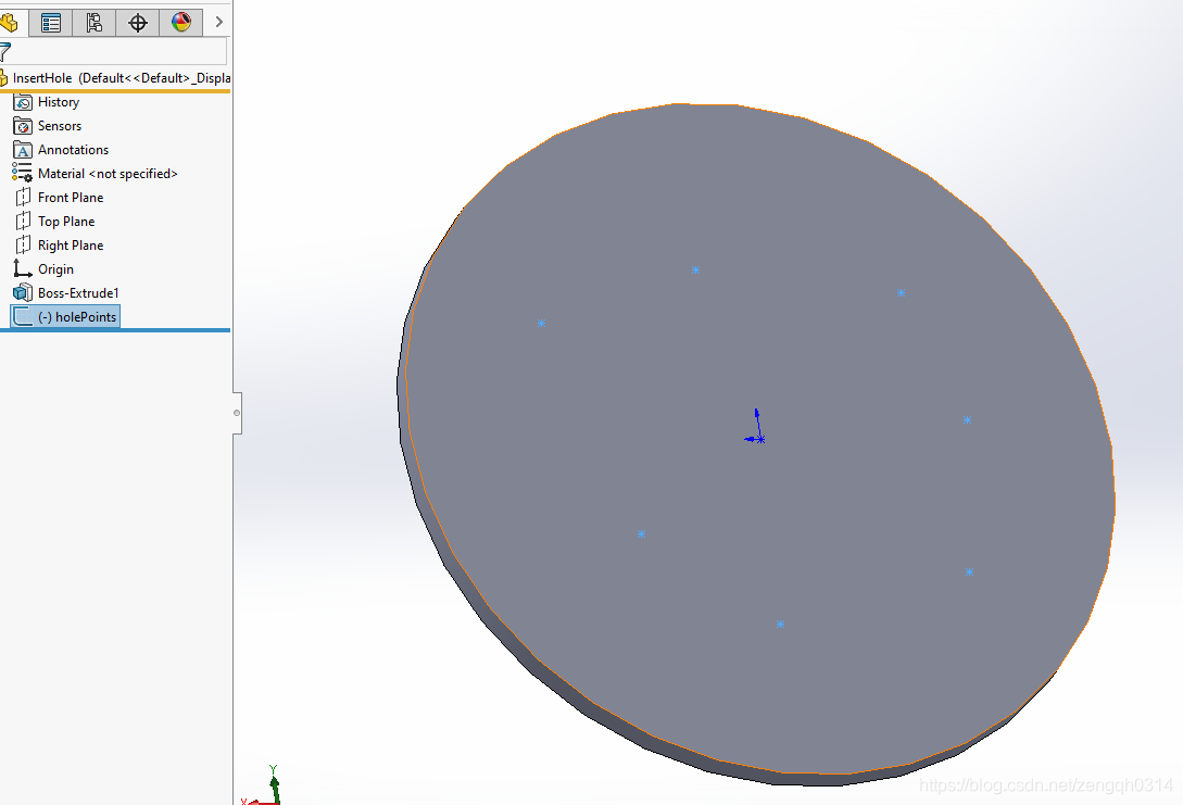
| 使用异形孔向导和草图点创建孔 |
Create_Holes_Using_Hole_Wizard_and_Sketch_Points_ |
| 创建孔向导孔 |
Create_Hole_Wizard_Hole_ |
| 创建Gtol复合框架 |
Create_Gtol_Composite_Frame_ |
| 为SOLIDWORKS 3D PDF创建常规表 |
Create_General_Table_for_SOLIDWORKS_3D_PDF_ |
| 创建完整的对称角度尺寸 |
Create_Full_Symmetrical_Angular_Dimension_ |
| 创建成型工具 |
Create_Forming_Tool_ |
| 在CommandManager中创建弹出窗口 |
Create_Flyouts_in_the_CommandManager_ |
| 使用草图轮廓创建拉伸特征 |
Create_Extrude_Feature_Using_Sketch_Contours_ |
| 创建爆炸视图 |
Create_Exploded_Views_ |
| 创建方程驱动曲线 |
Create_Equation-driven_Curve_ |
| 创建椭圆 |
Create_Ellipse_ |
| 创建图纸区域 |
Create_Drawing_Sheet_Zones_ |
| 创建拖动箭头操纵器 |
Create_Drag_Arrow_Manipulator_ |
| 创建细节圆和细节视图 |
Create_Detail_Circle_and_Detail_View_ |
| 创建派生模式特征 |
Create_Derived_Pattern_Feature_ |
| 创建派生或未衍生的草图 |
Create_Derived_or_Underived_Sketch_ |
| 在钣金零件中创建切割挤出 |
Create_Cut_Extrude_in_Sheet_Metal_Part_ |
| 使用工具主体创建切割扫描特征 |
Create_Cut-sweep_Feature_Using_Tool_Body_ |
| 使用圆形轮廓创建切割扫描特征 |
Create_Cut-sweep_Feature_Using_Circular_Profile_ |
| 通过参考点创建曲线 |
Create_Curve_Through_Reference_Points_ |
| 创建曲率连续可变圆角特征 |
Create_Curvature_Continuous_Variable_Fillet_Feature_ |
| 创建埋头孔 |
Create_Countersink_Slot_ |
| 创建角落救济特征 |
Create_Corner_Relief_Feature_ |
| 创建CommandManager选项卡和选项卡框 |
Create_CommandManager_Tab_and_Tab_Boxes_ |
| 创建子装配的圆形图案 |
Create_Circular_Pattern_of_Subassembly_ |
| 创建圆形图案 |
Create_Circular_Pattern_ |
| 创建破碎的视图 |
Create_Broken_View_ |
| 创建BreakOut部分 |
Create_BreakOut_Section_ |
| 从所选面创建实体 |
Create_Body_From_Selected_Faces_ |
| 创建块定义并插入块实例 |
Create_Block_Definition_and_Insert_Block_Instance_ |
| 创建双向线性模式 |
Create_Bidirectional_Linear_Pattern_ |
| 创建双向圆形图案特征 |
Create_Bidirectional_Circular_Pattern_Feature_ |
| 创建自动路线 |
Create_Auto_Route_ |
| 创建不对称椭圆圆角 |
Create_Asymmetric_Elliptic_Fillets_ |
| 创建角度尺寸 |
Create_Angular_Dimension_ |
| 创建和修改可变螺距螺旋 |
Create_and_Modify_Variable-pitch_Helix_ |
| 创建和修改移动面特征 |
Create_and_Modify_Move_Face_Feature_ |
| 创建和修改圆顶特征 |
Create_and_Modify_Dome_Feature_ |
| 创建和修改距离链模式特征 |
Create_and_Modify_Distance_Chain_Pattern_Feature_ |
| 创建和修改闭角特征 |
Create_and_Modify_Closed_Corner_Feature_ |
| 创建和修改腔体特征 |
Create_and_Modify_Cavity_Feature_ |
| 创建和编辑线性草图图案 |
Create_and_Edit_Linear_Sketch_Pattern_ |
| 创建和编辑圆形草图模式 |
Create_and_Edit_Circular_Sketch_Pattern_ |
| 创建和删除选择集 |
Create_and_Delete_Selection_Sets_ |
| 创建和转换非流形体 |
Create_and_Convert_Non-manifold_Bodies_ |
| 创建和访问曲线驱动的模式特征 |
Create_and_Access_Curve-driven_Pattern_Feature_ |
| 创建高级孔 |
Create_Advanced_Hole_ |
| 创建一个螺纹孔特征 |
Create_a_Thread_Feature_ |
| 创建独立于选择的标注 |
Create_a_Callout_Independent_of_a_Selection_ |
| 创建3D草图平面 |
Create_3D_Sketch_Plane_ |
| 创建3D Contact 特征 |
Create_3D_Contact_Feature_ |
| 创建3D边界框 |
Create_3D_Bounding_Box_ |
| 创建3点弧 |
Create_3_Point_Arc_ |
| 创建360度旋转特征 |
Create_360-degree_Revolve_Feature_ |
| 创建2D样条曲线 |
Create_2D_Spline_ |
| 在零件中创建,取消链接和清除显示状态 |
Create,_Unlink,_and_Purge_Display_States_in_Part_ |
| 复制文档及其依赖关系 |
Copy_Document_and_Its_Dependencies_ |
| 将组件与配件复制到组装 |
Copy_Components_With_Mates_To_Assembly_ |
| 使用Profile Center Mate复制组件 |
Copy_Component_With_Profile_Center_Mate_ |
| 复制和粘贴特征 |
Copy_and_Paste_Feature_ |
| 复制并粘贴图纸 |
Copy_and_Paste_Drawing_Sheet_ |
| 复制和粘贴外观 |
Copy_and_Paste_Appearances_ |
| 将面的边和内环转换为草图实体 |
Convert_Edges_and_Inner_Loops_of_Face_to_Sketch_Entities_ |
| 将绘图视图转换为草图 |
Convert_Drawing_Views_to_Sketches_ |
| 将曲线转换为3D草图 |
Convert_Curves_into_3D_Sketches_ |
| 约束草图 |
Constrain_Sketch_ |
| 比较所选对象及其持久参考ID |
Compare_Selected_Objects_and_Their_Persistent_Reference_IDs_ |
| 比较相同部件的不同版本中的DimXpert注释 |
Compare_DimXpert_Annotations_in_Different_Versions_of_Same_Part_ |
| 结合实体 |
Combine_Bodies_ |
| 清除显示状态 |
Clear_Display_States_ |
| 检查边缘是否有故障 |
Check_Edges_for_Faults_ |
| 更改换行特征面 |
Change_Wrap_Feature_Face_ |
| 更改草图块实例的可见性 |
Change_Visibility_of_Sketch_Block_Instances_ |
| 在指定配置中更改面上的纹理 |
Change_Texture_on_Face_in_Specified_Configuration_ |
| 更改孔表中的标签 |
Change_Tags_in_Hole_Table_ |
| 改变平面的草图 |
Change_Sketch_of_Plane_ |
| 改变螺旋的音高 |
Change_Pitch_of_Helix_ |
| 更改组件名称 |
Change_Name_of_Component_ |
| 改变线性模式 |
Change_Linear_Pattern_ |
| 更改配置中的尺寸公差 |
Change_Dimension_Tolerance_in_Configuration_ |
| 改变尺寸 |
Change_Dimension_ |
| 将组件更改为信封 |
Change_Component_to_Envelope_ |
| 在特定显示状态下更改组件的颜色 |
Change_Color_of_Component_in_Specific_Display_State_ |
| 将角度更改为补充角度 |
Change_Angle_to_Supplementary_Angle_ |
| 更改管理器窗格中的活动选项卡 |
Change_Active_Tab_in_Manager_Pane_ |
| 捕获3DView |
Capture_3DView_ |
| 调用编译的HTML帮助文件 |
Call_Compiled_HTML_Help_File_ |
| 计算零件中的转换 |
Calculate_Transformations_in_Part_ |
| 计算零件的环境影响 |
Calculate_Environmental_Impact_of_Part_ |
| 计算装配的环境影响 |
Calculate_Environmental_Impact_of_Assembly_ |
| 框选择草图 |
Box_Select_a_Sketch_ |
| 自动求解序列中的方程 |
Automatically_Solve_Equations_in_Sequence_ |
| 自动尺寸选择图纸视图 |
Autodimension_Selected_Drawing_View_ |
| Autodimension所有草图 |
Autodimension_All_Sketches_ |
| 自动插入中心标记 |
Auto_Insert_Center_Marks_ |
| 自动排列尺寸 |
Auto-arrange_Dimensions_ |
| 将文件附加到MBD 3D PDF |
Attach_Files_to_MBD_3D_PDF_ |
| 将注释附加到实体 |
Attach_Annotation_to_Entity_ |
| 附加注释 |
Attach_Annotation_ |
| 是否加载了装配配置 |
Are_the_Assembly_Configurations_Loaded_ |
| 按模型显示状态应用和删除纹理 |
Apply_and_Remove_Texture_By_Model_Display_State_ |
| 按显示状态应用和删除纹理 |
Apply_and_Remove_Texture_By_Display_State_ |
| 按配置应用和删除纹理 |
Apply_and_Remove_Texture_By_Configuration_ |
| 按组件显示状态应用和删除纹理 |
Apply_and_Remove_Texture_By_Component_Display_State_ |
| 按实体显示状态应用和删除纹理 |
Apply_and_Remove_Texture_By_Body_Display_State_ |
| 锚注 |
Anchor_a_Note_ |
| 分析GTol平面符号中的文本和几何 |
Analyze_Text_and_Geometry_in_GTol_Flat_Symbol_ |
| 对齐图纸视图 |
Align_Drawing_Views_ |
| 对齐辅助图纸视图 |
Align_Auxiliary_Drawing_View_ |
| 将水印添加到零件 |
Add_Watermark_to_Part_ |
| 添加工具栏 |
Add_Toolbars_ |
| 添加任务窗格视图 |
Add_Task_Pane_View_ |
| 将Spring添加到运动研究中 |
Add_Spring_to_Motion_Study_ |
| 添加Spotlight和获取灯光特征 |
Add_Spotlight_and_Get_Light_Feature_ |
| 添加参考尺寸 |
Add_Reference_Dimension_ |
| 将对象添加到选择列表 |
Add_Objects_to_Selection_List_ |
| 添加菜单和菜单项 |
Add_Menu_and_Menu_Item_ |
| 添加爆炸步骤 |
Add_Explode_Step_ |
| 添加方程式 |
Add_Equations_ |
| 添加等式并评估所有 |
Add_Equation_And_Evaluate_All_ |
| 添加派生配置 |
Add_Derived_Configurations_ |
| 添加贴花 |
Add_Decal_ |
| 将阻尼器添加到运动算例中 |
Add_Damper_to_Motion_Study_ |
| 在BOM中添加配置并提升子组件 |
Add_Configuration_and_Promote_Child_Components_in_BOM_ |
| 添加组件 |
Add_Components_ |
| 添加组件和配合 |
Add_Component_and_Mate_ |
| 添加对Assembly Component的评论 |
Add_Comment_to_Assembly_Component_ |
| 将按钮添加到任务窗格 |
Add_Buttons_to_Task_Pane_ |
| 将按钮添加到上下文相关菜单 |
Add_Button_to_Context-sensitive_Menu_ |
| 将气球添加到堆积的气球 |
Add_Balloon_to_Stacked_Balloon_ |
| 将Autoballoon添加到面部 |
Add_Autoballoon_to_Face_ |
| 添加属性到属性并包含在库特征中 |
Add_Attribute_to_Feature_and_Include_in_Library_Feature_ |
| 从Pack and Go添加和删除文件 |
Add_and_Remove_Files_from_Pack_and_Go_ |
| 添加和获取属性扩展 |
Add_and_Get_Property_Extension_ |
| 添加和编辑未对齐的对称同心伴侣 |
Add_and_Edit_Misaligned_Symmetric_Concentric_Mate_ |
| 添加和编辑距离配合 |
Add_and_Edit_Distance_Mate_ |
| 添加和删除特定显示状态的材料 |
Add_and_Delete_Materials_from_Specific_Display_States_ |
| 沿Z尺寸添加到3D草图 |
Add_Along_Z_Dimension_To_3D_Sketch_ |
| 沿Y尺寸添加到3D草图 |
Add_Along_Y_Dimension_To_3D_Sketch_ |
| 沿X尺寸添加到3D草图 |
Add_Along_X_Dimension_To_3D_Sketch_ |
| 将ActiveX选项卡添加到模型视图 |
Add_ActiveX_Tabs_to_Model_View_ |
| 将ActiveX选项卡添加到FeatureManager设计树 |
Add_ActiveX_Tabs_to_FeatureManager_Design_Tree_ |
| 将ActiveX选项卡添加到FeatureManager设计树 |
Add_ActiveX_Tab_to_FeatureManager_Design_Tree_ |
| 使用加载项将.NET控件添加到SOLIDWORKS |
Add_.NET_Controls_to_SOLIDWORKS_Using_an_Add-in_ |
| 激活SOLIDWORKS CommandManager选项卡 |
Activate_SOLIDWORKS_CommandManager_Tab_ |
| 激活装配中的智能特征 |
Activate_Smart_Features_in_an_Assembly_ |
| 激活Property Manager页面选项卡 |
Activate_Property_Manager_Page_Tab_ |
| 访问和释放对边缘的访问权限 |
Access_and_Release_Access_to_Edges_ |
